Published 2021/12/21
Foreword
While I give a cursory introduction to some programming and linear algebra concepts I often neglect defining exact behaviours (for example how vectors behave). I assume that you the reader either already know about these or are willing to research these topics yourself.
The code referenced in this post can be found in both C++ and Rust on my Github (The latest version can be found here but there is no guarantee that it still reflects this post).
I must also thank the online book Raytracing in one Weekend, my follow along of the book taught me the working principles of raytracers and heavily guided my first raytracer written in C++ which can be found here.

In the real world light is emmited by some emmisive object, it then travels in (mostly) straight lines, bouncing off objects - where certain wavelengths are absorbed, producing different colours - until all the light is absorbed. Light that is absorbed by our eyes is turned into electrical signals that are percieved as images in the brain. Raytracing emulates this process backwards in order to make digital images. A ray is cast out from the point of view and the objects it bounces off kept track of in order to determine a colour for the direction that the ray is cast in.
In order to build a raytracer we first need to define a vector. A vector is a quantity with an associated magnitude and direction. For three dimensions it is easiest to define a vector $\vec a$ with three values $x$, $y$, $z$, one for each axis in 3D space, mathematically we denote this
$$\vec a = (x, y, z)$$
Additionaly we define a set of useful properties including itemwise addition and subtraction, scaling, vector magnitude, and the dot and cross products respectively.
$$\vec u = (a, b, c), \ \vec v = (d, e, f)$$
$$\begin{align*} \vec u + \vec v &= (a+d, b+e, c+f)\\ \vec u - \vec v &= (a-d, b-e, c-f)\\ t\vec u &= (ta, tb, tc)\\ ||\vec u|| &= \sqrt{a^2 + b^2 + c^2}\\ \vec u \cdot \vec v &= ad + be + cf\\ \vec u \times \vec v &= (bf - ce, -(af - cd), ae-bd) \end{align*} $$
In a raytracer 3D vectors are often used to define points in space and colours in addition to typical vector values.
From vectors we can then derive an equation for a line, which are commonly reffered to as rays in ray tracing. All lines have a point of origin $\vec o$, and a direction $\vec d$ they point in. By multiplying the direction vector $\vec d$ by some scalar $t$ and adding it to the origin vector $\vec o$ we can produce any point $\vec r$ on the line $R(t)$. Mathematically
$$\begin{align}\vec r = R(t) = \vec o_\text{ray} + t\vec d\end{align}$$
Now that we’ve defined rays we can cast them from our viewport and note what they intersect with in order to draw an image. For this we’ll need to define our first object that rays can intersect, since spheres are a common choice we will start with them.
Mathematically speaking a sphere is defined by all the points in space a certain distance - the radius ($r$) - from a central point ($\vec o$). Relative to the point $\vec o$ we can derive an equation that is satisfied only for points on the surface of the sphere
$$\begin{equation}x^2+y^2+z^2 = r^2\end{equation}$$
If we let $\vec p$ be some vector relative to the point $\vec o$ such that $\vec p = (x, y, z)$ we note that $\vec p\cdot \vec p = x^2+y^2+z^2$ and thus if the point $\vec p$ is on the surface of the sphere $\vec p \cdot \vec p = r^2$ by Equation 2.
Using this we can determine if a point $\vec r$ on ray as defined in Equation 1 is on the sphere. To do this we note that by the definition of $\vec p$, and Equations 1 and 2
$$\begin{align*} && \vec o_\text{circle} + \vec p &= \vec r\\ && \vec p &= \vec r - \vec o_\text{circle}\\ &&&= \vec o_\text{ray} + t\vec d - \vec o_\text{circle}\\ && r^2 &= \vec p \cdot \vec p\\ &\Rightarrow& r^2 &= (\vec o_\text{ray} + t\vec d - \vec o_\text{circle}) \cdot (\vec o_\text{ray} + t\vec d - \vec o_\text{circle})\\ \end{align*}$$
$$\begin{align}\Rightarrow t^2\vec d \cdot \vec d +2t\vec d \cdot (\vec o_\text{ray} - \vec o_\text{circle}) - (\vec o_\text{ray} - \vec o_\text{circle}) \cdot (\vec o_\text{ray} - \vec o_\text{circle}) - r^2 = 0\end{align}$$
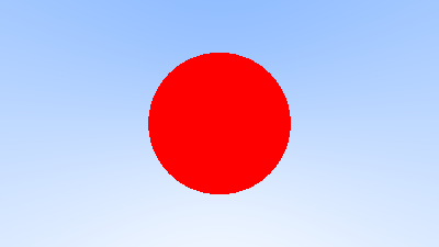
We can solve Equation 3 with the quadratic equation in order to determine if and where a ray intersects a sphere. Using this we can create the most rudimentary form of raytracer, one that casts a ray from the camera and determines if it intersects anything, if it does then colours the pixel as specified by the object that was intersected (Figure 2).

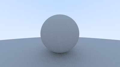
This isn’t beautiful. In order to improve this we use a few vital techniques.
- Anti-aliasing: Take multiple samples of a pixel with random noise in each sample, this means that edges will blur slightly making images look "smoother".
- Scattering: Calculate surface normals and trace a new ray off the surface, record any interactions and modify the colour of the pixel based on furth interactions of scattered rays.
Figure 3 shows these improvements.

We can also implement different material types and define how they cause rays to scatter, these are methods I have spent only enough time on to use rather than fully understand so I defer to Raytracing in one Weekend at this time.
While spheres look very nice in our renders, a far more versatile shape is the humble triangle. It feels quite natural to define a triangle by its three vertices so this is how we will proceed. Let us name them $\vec v_1$, $\vec v_2$, and $\vec v_3$. To determine if a ray intersects a triangle let us first start by determining where a ray intersects the plane of the triangle. We know that a point $\vec r$ on a plane will satisfy the equation
$$\begin{align}\vec r \cdot \vec n = \vec r_0 \cdot \vec n\end{align}$$
Where $\vec n$ is the plane’s normal (determined by the cross product of $\vec v_2 - \vec v_1$ and $\vec v_3 - \vec v_1$), and $\vec r_0$ is a point on the plane. Since $\vec r = \vec o_\text{ray} + t\vec d$ per Equation 1
$$\begin{align*} \vec r \cdot \vec n &= \vec r_0 \cdot \vec n\\ (\vec o_\text{ray} + t\vec d) \cdot \vec n &= \vec r_0 \cdot \vec n\\ \vec o_\text{ray} \cdot \vec n + t\vec d \cdot \vec n &= \vec r_0 \cdot \vec n \end{align*}$$
$$\begin{align} \Rightarrow t = \frac{\vec r_0 \cdot \vec n - \vec o_\text{ray} \cdot \vec n}{\vec d \cdot \vec n} \end{align}$$
Plugging $t$ back into Equation 1 gives the point $\vec r$ where the ray intersects the plane. It must now be determined whether this point $\vec r$ lays within the triangle. This can be done with an angle check from each vertice.
For each vertice three vectors originating from the vertice are produced
$$\begin{align*} \vec a &= \vec v_2 - \vec v_1\\ \vec b &= \vec v_3 - \vec v_1\\ \vec c &= \vec r - \vec v_1 \end{align*}$$
Vectors $\vec a$ and $\vec b$ bound the triangle and $\vec c$ is the position of the point $\vec r$ relative to the vertice in question. For the point $\vec r$ to be in the triangle the angle - per Equation 6 - between $\vec a$ and $\vec c$ must be less than or equal to the angle between $\vec a$ and $\vec b$ for all three vertices.
$$\begin{align} \cos\theta = \frac{\vec u \cdot \vec v}{||\vec u || ||\vec v ||} \end{align}$$
In C++ this might look something like
// Triangle-Ray intersection in C++ (Paraphrased)
// Full code available: https://github.com/JHay0112/raytracing/blob/v0.1.0/triangle.h
bool triangle::hit(const ray& r) const {
    // Find the plane's normal choosing v1 as origin
    vec3 n = cross(vertices[1] - vertices[0], vertices[2] - vertices[0]);
    vec3 r_0 = vertices[0];
    // Now can produce scalar form of plane and get val of t where point is on it
    double t = dot((r_0 - r.origin()), n)/dot(r.direction(), n);
    // Check that the point is in the triangle
    // Get the point
    point3 p = r.at(t);
    // First a check from v0
    vec3 v0_v1 = vertices[1] - vertices[0];
    vec3 v0_v2 = vertices[2] - vertices[0];
    vec3 v0_p = p - vertices[0];
    double v0_angle = angle_between(v0_v1, v0_v2);
    double v0_p_angle = angle_between(v0_v1, v0_p);
    if (v0_p_angle > v0_angle)
        return false;
    // Check from v1
    ...
    // Check from v2
    ...
    // Passed this far must be in triangle
    return true;
}
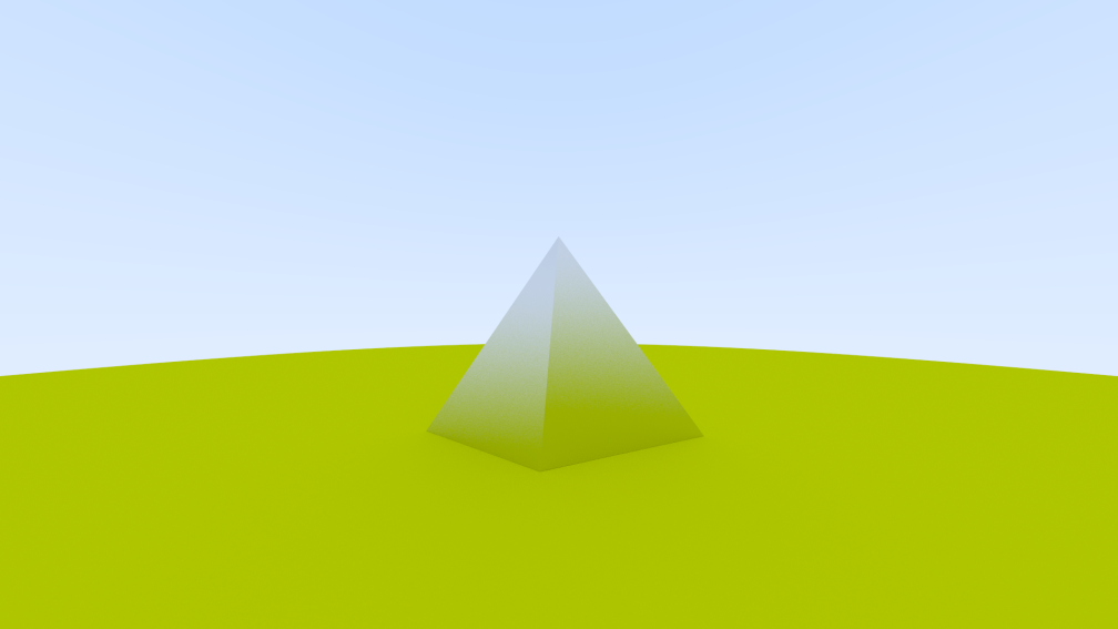
With this implemented it’s possible to make images that utilise triangles like the pyramid in Figure 1.
This project immensely deepened my knowledge of C++ and computer graphics, while I’m still quite a novice this has inspired me to think bigger while programming and to reach out into some new areas. I enjoyed this experience so much for C++ that I’ve decided to do it all again in Rust. Rust is a language that I have meant to learn for sometime and so far I’ve found it to live up to the hype. While not a trivial learning curve at first I’ve found Rust’s language design rewards thoroughly written and effecient programs. The first version of my Rust raytracer (admittedly triangle free) can be found here and ongoing development here.
I’m not sure where the future of this project is headed, but I do have a list of ideas I’m going to play around with and if I build something I’m proud of no doubt will there be another blog post about it. In no particular order:
- Light emmiting objects.
- Positionable cameras.
- Threading.
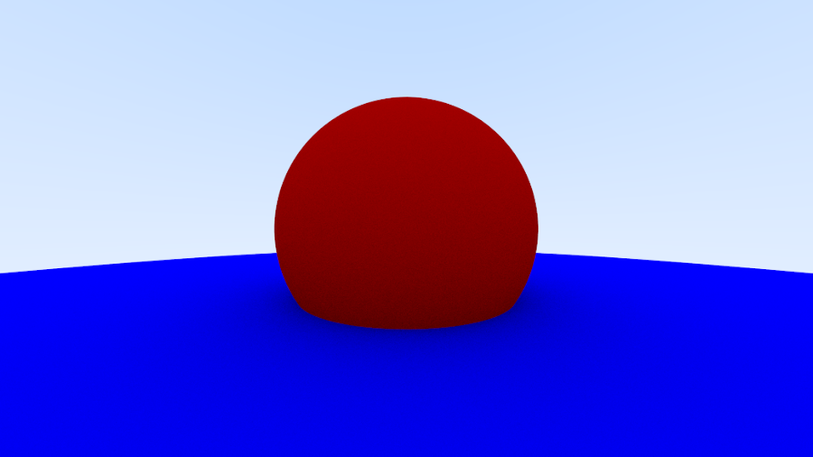
As an added bonus for making it to the very end of the post, a final raytraced image (Figure 4), this one from my Rust raytracer.
